AV1 decoder model
Published June 24, 2020.
Andrey Norkin is with Netflix Encoding Technologies.
Why codecs need decoder models
Most modern video codecs have some form of a decoder model. It may be called a video buffering verifier (VBV), as in MPEG-2, or a hypothetical reference decoder (HRD), as in H.264/AVC and HEVC/H.265. Decoder models improve interoperability. A decoder model allows to determine whether a bitstream can be decoded by a particular decoder. These models may also provide a decoder with instructions on when to start decoding a frame to be able to display it on time.
Typically, a video decoder declares support of a certain profile and level. A profile may specify video formats with respect to the bit depth and chroma subsampling and a set of coding tools that a decoder needs to support to decode a bitstream. A level describes quantitative characteristics of a video bitstream, such as resolution, frame rate, and bitrate. It is critically important for a video codec ecosystem that decoders claiming support of a certain level were capable of decoding any bitstream that complies with requirements for this level and that content providers and encoder manufacturers could check whether streams they generate comply with these requirements.
To achieve these goals, AV1 specification, developed by the Alliance for Open Media (AOM), defines a decoder model coupled with a system of profiles and levels. AV1 decoder model includes a smoothing/bitstream buffer, a decoding process, and operations on the decoded frame buffers. This post can serve as an introduction to the parts of the AV1 specification related to the decoder model and levels. The rest of this post describes some basic AV1 concepts, the AV1 decoder model, and gives reasons behind decisions made when developing it. For more details on the decoder model, the readers are referred to the AV1 specification.
High level structure of AV1 bitstream
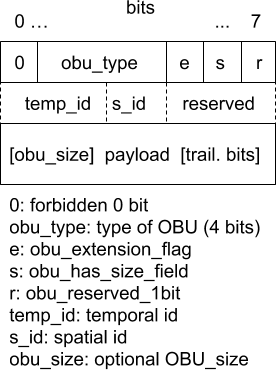
At a higher level, AV1 structures are packetized in Open Bitstream Units (OBU). Each OBU has a header, which provides information identifying its payload (see Fig. 1). Examples of OBU types that can be present in AV1 video bitstreams are sequence header OBU, frame header OBU, metadata OBU, temporal delimiter OBU, and tile group OBU. A frame OBU consists of a frame header and tile group OBUs packed into one OBU to provide a more efficient representation of a common structure where the frame header data is immediately followed by the frame or tile group data.
AV1 frame headers can be classified in two main types based on the value of a syntax element show_existing_frame. Frame headers with show_existing_frame equal to 0 are regular frames that need to be decoded. Frame headers with show_existing_frame equal to 1 specify a command to display a previously decoded frame (indicated by frame_to_show_map_idx) at the presentation time specified in this frame header. This mechanism facilitates frame reordering when the decoding order is different from the display order.
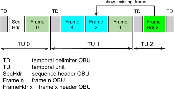
Another AV1 concept is temporal unit (TU), which consists of a temporal delimiter OBU and all OBUs following this and preceding the next temporal delimiter OBU. TUs always follow increasing display order. If scalability is not used, a TU includes exactly one shown frame, i.e. a frame with show_existing_frame equal to 1 or with show_frame equal to 1. If scalability is used, all shown frames from different scalable layers in a TU correspond to the same presentation time. A TU can also include frames with the show_frame flag equal to 0. Such frames are decoded but not immediately displayed. They are used to support frame reordering as described above. Alternatively, an overlay frame can be send, which encodes the difference between a previously decoded frame, called the alternative reference frame (ARF), and the source frame. This aspect of the AV1 bitstreams resembles the VP9 codec with its superframes.
An example of segmenting a bitstream into temporal units is shown in Fig. 2. In the figure, the frame numbering is in the display order. The bitstream uses a 4-frame hierarchical-B prediction structure with three temporal layers. Frames with show_frame equal to 0 are shown as cyan boxes, frames with show_frame equal to 1 as dark green boxes. FrameHdr 2 is a frame header with show_existing_frame flag equal to one, this frame points to a previously decoded Frame 2.
Smoothing buffer
The smoothing buffer is part of the AV1 decoder and is used to store an AV1 bitstream until the compressed data is consumed by the decoder. The buffer is described by the so-called "leaky bucket" model. The leaky bucket analogy is related to operation of the encoder, where compressed frames are dumped in the buffer in chunks while the data leaves the buffer continuously at a constant rate. The decoder buffer is a counter-part of the encoder one. Note that smoothing buffer is internal to the decoder. Often, decoding systems would have other buffers at a higher level, which are outside the scope of AV1 specification. From the decoder model perspective, higher level buffers could be considered parts of the transmission channel contributing to the overall delay. For example, buffering related to the adaptive streaming would be considered part of the transmission channel from the decoder viewpoint and is not discussed in this post. Also, the encoded bitstream may often be prepared in advance, which can makes the delay rather long. However, such a long delay is generally not a problem for the model since it is cancelled out in the equations.
The smoothing buffer makes sure that the decoder has enough internal memory to store the data of the arriving (or read) bitstream. It also ensures that the compressed data of the next frame is in the buffer when the decoder needs it. The size of the smoothing buffer limits variations of the instantaneous bitrate and restricts timing of the frame data consumption.
The AV1 decoder model only supports the variable bitrate (VBR) mode of operation and not a constant bitrate (CBR) mode. The VBR mode of the decoder model is an abstraction, where the rate is alternating between the maximal level bitrate and zero. It may sound restrictive. However, this model is adequate for the task of making sure the bitstream matches decoder capabilities, where the worst case is important.
A diagram of the smoothing buffer fullness over time is shown in Fig. 3. The clock starts with the arrival of the first bit related to frame 0. The slope of the slanted line corresponds to the rate of bits arrival. Removal[ i ] corresponds to the moment when the data of frame i is removed from the buffer and decoding of frame i begins. Note that there can be periods of time when new bits do not arrive, such as time after Removal[ 1 ]. This matches periods of time when the encoder did not have bits to send, i.e. when the encoder buffer was empty.
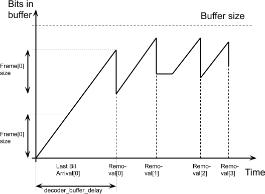
Removal[ i ] for frame i is defined depending on one of the two decoding modes. In the decoding schedule mode, these values are signaled in the bitstream. In the resource availability mode, Removal[ i ] are derived based on the decoder operation. The start of the decoding, i.e. Removal[ 0 ], is determined by the variable decoder_buffer_delay in both modes.
Bits removed from the decoded buffer at time Removal[ i ] belong to the decodable frame group (DFG) i, i.e. all OBUs between the end of the last OBU associated with frame i − 1 and the end of the last OBU associated with frame i. OBUs in a DFG may include sequence header OBUs, frame and tile group OBUs, frame header OBUs, and metadata OBUs.
The arrival of the first bit of the DFG i in the smoothing buffer is determined by FirstBitArrival[ i ], which is found as follows:
FirstBitArrival[ i ] = max ( LastBitArrival[ i − 1 ], LatestArrivalTime[ i ] ).
Respectively, arrival of the last bit of the DFG i is found asLastBitArrival[ i ] = FirstBitArrival[ i ] + CodedBits[ i ] ÷ BitRate.
Finally, LatestArrivalTime[ i ] is determined asLatestArrivalTime[ i ] = ScheduledRemoval[ i ] − ( encoder_buffer_delay + decoder_buffer_delay ) ÷ 90 000.
Good explanations on the relationship between the encoder_buffer_delay and decoder_buffer_delay in the latter expression along with other useful information can be found in Ribas-Corbera et al, 2003. The model assumes an encoder with a smoothing buffer that sends bits at a constant rate and a decoder with a smoothing buffer that receives bits at that bitrate. A general intuition for the sum of encoder_buffer_delay and decoder_buffer_delay is that it determines a delay between the encoding and decoding of a frame and therefore limits a "window" over which the bitstream is stored in the decoder buffer (the transmission over the network / channel is excluded). Since the buffer size is set to 1 second of the bitstream at maximal level bitrate, it is not recommended for the sum of this two variables to exceed 90 000, which corresponds to 1 second in the clock frequency.
When low_delay_mode flag is equal to 1, the decoder operates in the low-delay mode, where the frame data may not be available in the buffer at the scheduled removal time, in which case the removal time is delayed until the data is available in the buffer.
Except when in the low delay mode, the smoothing buffer shall not underflow. The smoothing buffer shall not overflow either. These restrictions apply to all conformant bitstreams.
Decoded frame buffer
The frame buffer is used to store decoded frames so that they could be used in inter-frame prediction or displayed later. AV1 defines a buffer pool that represents the storage area for frame buffers. A diagram for management of AV1 frame buffers is shown in Fig. 4. AV1 specification requires a decoder to support ten physical frame buffers. Slots for the frame buffers shall be capable of storing a frame at the maximal resolution for the corresponding level. Virtual buffer index (VBI) is used for referencing frames in the inter-picture prediction. VBI can store 8 indices to frames in the frame buffers pool. Different VBI entries are allowed to point to the same buffer slot. An empty VBI entry contains value −1. The current frame buffer index (cfbi) stores an index to the frame buffer where the current frame is being decoded. Note that there is one "extra" physical frame buffer, which can be used to hold a frame for the display purpose.
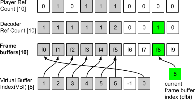
Arrays DecoderRefCount and PlayerRefCount (top two rows in Fig. 4) keep track of whether a frame buffer is still needed by the decoding and display processes, respectively. The DecoderRefCount tracks the number of references to the frame buffer in the VBI and is updated by the syntax element refresh_frame_flags, whereas the PlayerRefCount is set to 0 when the frame has been displayed at its last presentation time. Empty frame buffers and corresponding counters are shown in Fig. 4 as white squares.
The frame buffer imposes restrictions on the decoding and presentation of video frames thus limiting what prediction structures and frame reordering can be used by the encoder. In general, 10 frame buffers allow supporting rather complicated prediction structures. The decoder model verifies that the frame is available when it should be displayed, and there is a free slot in the buffer pool when a frame should be decoded.
Decoding process
AV1 decoding process at higher level
The decoding process of the AV1 decoder model ties together operations on the smoothing buffer and the decoder frame buffer. In particular, the decoder model determines when a frame decoding starts and the frame bits are removed from the smoothing buffer, which instantaneously decreases fullness of the smoothing buffer by the corresponding amount. The decoder model also calculates when the decoding finishes and the decoded frame is added to the frame buffers. It also determines when the frame is output for the display and removed from the buffer.
One characteristic of the AV1 is an extensive use of alternative reference frames (ARF), i.e. frames which are used as prediction references but never displayed. In addition, AV1 supports reference picture scaling and scalability in the Main profile. This means that the model should accommodate different times needed for frame decoding and support different rates of frames decoding and display. Note that even though H.264 and HEVC allow non-displayable pictures, this is not a typical use of these codecs, whereas in AV1 this is a typical use case that needs to be well supported by the decoder model.
An example of the encoding with ARF is shown in Fig. 5. The figure shows hierarchical-B style encoding with the sub-GOP size of 4. Displayable frames are shown as gray rectangles. The alternative reference frame (ARF), denoted as the white rectangle, is not displayed. Usually, this frame is a filtered version of the frame in the same temporal position, which brings advantages for inter-frame prediction. Since the ARF is low-pass filtered, an overlay frame (OL in Fig. 5) can be encoded using ARF as a predictor. The overlay frame adds high-frequency and texture information.
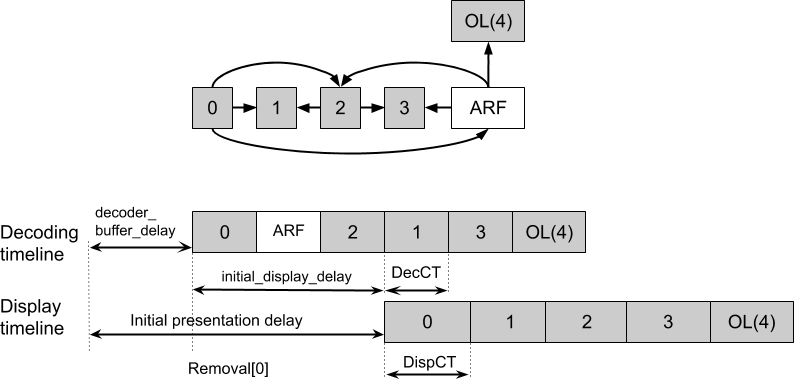
To accommodate support of alternative reference frames and frames of different resolution, the following features have been introduced in the AV1 decoder model:
- A possibility to use a different number of time units in the decoder and display clock ticks. Note that display clock tick (DispCT) and decoding clock tick (DecCT) in Fig. 5 have different length since the decoding and display rates are different. The same time scale base is used in both decoder and display ticks and the clocks are synchronized
- Decoding a frame does not happen instantaneously and can take different time depending on the frame resolution and other factors
One can see that the decoding and display timelines in Fig. 5 use different clock ticks. Obviously, decoding of each frame needs to be completed before the frame can be displayed. To make sure a future frame is available, an encoder can use initial_display_delay_minus_1, which specifies the number of decoded frames minus one that should be available in the frame buffers before the first frame is displayed. This parameter offsets the display process relative to the decoding. If not signaled, the value of initial_display_delay_minus_1 is inferred as BUFFER_POOL_MAX_SIZE − 1. The overall presentation delay includes the decoder_buffer_delay, which is the same variable as in Fig. 3, the time between the first bit arrival and the start of decoding of frame 0, namely Removal[ 0 ].
Time needed to decode frame i is determined as
TimeToDecode[ i ] = lumaSamples[ i ] ÷ MaxDecodeRate,
where MaxDecodeRate is measured in samples/sec and specified for each decoder level. In its turn, lumaSamples are calculated for intra predicted frames aslumaSamples[ i ] = UpscaledWidth[ i ] * FrameHeight[ i ].
UpscaledWidth is the width of the frame after the optional super-resolution tools has been used. For inter predicted frames, this number is determined as follows to take into account possible motion compensation from a frame with higher resolution in case of the reference picture resampling
lumaSamples[ i ]= max_frame_width * max_frame_height.
In a scalable bitstream, lumaSamples is determined as a product of the maximum width and height for the current scalable layer.
In addition to knowing how long a frame decoding can take, the decoder model needs to determine when the decoding starts and the compressed frame is removed from the smoothing buffer, i.e. times Removal[ i ]. AV1 has two different modes with respect to how Removal[ i ] are computed. These two modes are the resource availability mode and decoding schedule mode described in the following.
Resource availability mode
In the resource availability mode, a frame is decoded immediately after the previous frame decoding has been completed if there is a free slot available in the decoded frame buffer. Otherwise, the frame is decoded when a slot is freed up. If a bitstream is below decoder's maximal level constraints, the frames are decoded one after another until they fill up all available frame buffers, after which the pace of decoding slows down. Then, decoding of the next frame only happens after a decoded frame buffer slot frees up. Removal time of frame 0 is determined by the decoder_buffer_delay:
Removal[ 0 ] = decoder_buffer_delay ÷ 90 000.
To use the resource availability mode, the following parameters should be set in the bitstream: timing_info_present_flag = 1, decoder_model_info_present_flag = 0, and equal_picture_interval = 1. The flag equal_picture_interval equal to 1 means that the constant frame rate is used and presentation times are not signaled. Instead presentation times are derived from the frame rate and the initial_display_delay_minus_1. The decoding timing Removal[ i ] is determined by the moments when a decoded frame buffer becomes available, and are not signaled either. Some decoder model parameters take default values in the resource availability mode, for example encoder_buffer_delay = 20 000, decoder_buffer_delay = 70 000, and low_delay_mode_flag = 0.
Decoding schedule mode
In the decoding schedule mode, the decoding times Removal[ i ] are signaled in the video bitstream in addition to the frame presentation times. The model flexibly defines when a frame is removed from the smoothing buffer and decoded, and when the frame is displayed. In addition to using a constant frame rate, this model can support varying frame rates by signaling frame presentation times explicitly. In addition to that, the decoder clock tick DecCT along with decoder_buffer_delay, encoder_buffer_delay, and ScheduledRemovalTiming[ i ] are also signaled in this decoding mode.
The scheduled removal timing for frame i is derived in this mode as follows.
ScheduledRemovalTiming[ 0 ] = decoder_buffer_delay ÷ 90 000.
ScheduledRemovalTiming[ i ] = ScheduledRemovalTiming [ PrevRap ] + buffer_removal_time[ i ] * DecCT,
where PrevRap is the previous random access point (RAP). If frame i corresponds to a RAP, but is not the first frame in the bitstream, PrevRAP corresponds to the previous RAP. The random access point here means a location in a bitstream, which the bitstream can be decoded from. It usually corresponds to a key frame and should contain all necessary information to start decoding a bitstream, including a sequence header.
Unless the decoder operates in the low delay mode, the removal times coincide with the scheduled removal times
Removal[ i ] = ScheduledRemovalTiming[ i ].
To support scalability, the decoder model is signaled separately for each operating point (OP). An operating point is related to decoding of a certain scalable layer and the lower scalable layers necessary for its decoding. Higher operating points in a bitstream may require using decoders conformant to higher levels.
Difference between two modes of the decoder model
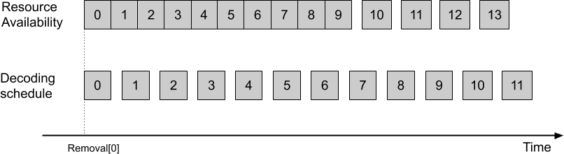
One can notice that the decoder operation in the decoding schedule mode is a superset of the decoder operation in the resource availability mode. It should be possible for an encoder to signal the same Removal[ i ] that would have been derived in the resource availability mode. Decoding schedule mode can also be used to control the frame decoding schedule. Fig. 6 shows a scenario when the bitstream requirements are below the maximal level capabilities. In the resource availability mode, the frames are decoded one after another, and when there are no free slots left in the frame buffer, the decoding slows down. In the decoding schedule mode, it is possible to decode the bitstream at a constant pace. Note that when the decoder is operating close to its maximal capabilities (e.g. the bitstream is close to the level limit in terms of the resolution and frame rate), the decoder operations in both modes are similar.
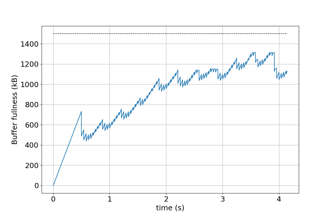
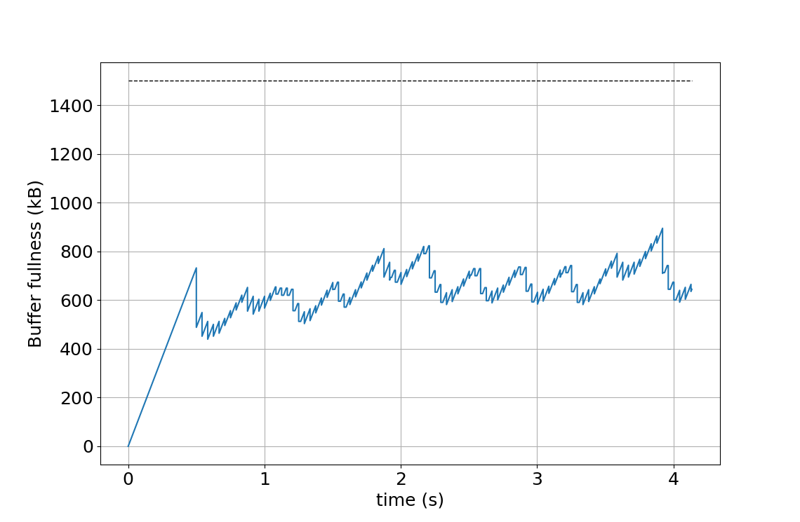
Additionally, the decoding schedule mode can be used to get a better control over the smoothing buffer fullness (see Fig. 7). The figure illustrates how the smoothing buffer fullness changes over time depending on values of parameters encoder_buffer_delay and decoder_buffer_delay. The illustration uses a 1920×1080 video at 24 frames per second, encoded as a level 4.0 AV1 bitstream. Frame sizes are chosen compliant with a 8-frame hierarchical prediction structure; the example is constructed and does not represent any particular video encoding. The maximal smoothing buffer capacity is shown by the horizontal dashed line. Fig. 7(a) shows the buffer fullness over time with encoder_buffer_delay = 20 000, decoder_buffer_delay = 70 000, which are equal to the default values used in the resource availability mode. By reducing the decoder_buffer_delay, it is possible to start decoding earlier, which is demonstrated in Fig. 7(b) by using both encoder_buffer_delay and decoder_buffer_delay equal to 45 000. Note that the sum of the encoder_buffer_delay and decoder_buffer_delay is equal to 90 000, which corresponds to 1 second, the duration of a bitstream at the maximum level bitrate that the smoothing buffer can hold. It is also possible to keep the buffer fullness at a lower level, which is demonstrated in Fig. 7(c) by using parameters encoder_buffer_delay = 10 000, decoder_buffer_delay = 45 000.

Presentation times
The presentation time for AV1 is signaled with the frame_presentation_time syntax element. The actual presentation time also depends on the InitialPresentationDelay and is computed as follows:
PresentationTime[ 0 ] = InitialPresentationDelay,
PresentationTime[ j ] = PresentationTime[ PrevPresent ] + frame_presentation_time[ j ] * DispCT,
where PrevPresent corresponds to the index associated with the last key frame random access point (RAP) if the previous RAP is a key frame RAP, or to a delayed recovery point if the previous RAP is a delayed RAP (i.e. the one corresponding to the forward key frame / open GOP). The delayed recovery point corresponds to the time when the key frame in the open GOP is displayed.
In its turn, the InitialPresentationDelay is determined as follows:
InitialPresentationDelay = Removal [ initial_display_delay_minus_1 ] + TimeToDecode [initial_display_delay_minus_1 ].
In other words, the InitialPresentationDelay is the time when there are initial_display_delay_minus_1 + 1 decoded frames in the frame buffer.
When equal_picture_interval is equal to 1, the constant frame rate mode is used, and the presentation times for frames j greater than 0 are derived as follows:PresentationTime[ j ] = PresentationTime[ j − 1 ] + ( num_ticks_per_picture_minus_1 + 1 ) * DispCT,
where PresentationTime[ j − 1 ] refers to the previous frame in presentation order. PresentationTime[ 0 ] is derived as above.
Decoder model signaling
The decoder model parameters are mostly signaled at the sequence and frame level. A sequence header may include a timing_info() structure, which contains display timing information. The basic decoder model information is in the decoder_model_info() structure. In addition to that, one or more operating points (OP) can be signaled in the sequence header for a scalable bitstream. Each OP corresponds to a decoder level necessary to decode that OP and can be optionally assigned a set of the decoder model parameters.
The timing_info() structure contains the time scale and the number of time units in the display tick num_units_in_display_tick, whereas the decoder_model_info() structure contains the number of units in the decoder tick num_units_in_decoding_tick along with lengths of other decoder model syntax elements. These two syntax elements define duration of the DispCT and DecCT variables as:
DispCT = num_units_in_display_tick ÷ time_scale,
DecCT = num_units_in_decoding_tick ÷ time_scale.
The operating_parameters_info() structure contains the encoder_buffer_delay and decoder_buffer_delay for the operating point as well as the low delay mode flag. If the decoder model is used, buffer_removal_time in units of the decoding clock ticks can be signaled in the frame header for selected operating points. The temporal_point_info() structure in the frame header contains the frame_presentation_time syntax element, which signals the display time of a frame in display clock ticks.AV1 levels
On the moment of writing this post, AV1 specification defines levels 2.0 to 6.3, which roughly span decoder capabilities necessary to decode videos from 426×240@30fps to 7680×4320@120fps. The decoder model establishes bitstream and decoder conformance to a certain level. AV1 levels declare support of a certain frame resolution (a number of samples in a frame), decoding and display sample rates. Other level parameters relevant to the decoder model include maximal bitrate and the frame header rate. Levels can belong to one of two tiers (main and high), with high tier having higher maximal bitrate than the main tier and targeted to professional and special applications.
The maximal bitrate directly defines the size of the smoothing buffer, which shall be able to hold up to 1 second of a compressed stream at the maximal level bitrate. This imposes a restriction on the peak bitrate since no buffer overflow or underflow is allowed for a conformant bitstream. In addition to that, the minimal compression ratio for a frame is also specified.
Bitstreams claiming conformance to a certain level shall not violate the constraints if passed through the decoder model. A conformant decoder, in its turn, shall be capable of decoding any conformant bitstream of the same or lower level as long as the bitstream complies with the AV1 specification, which includes passing the decoder model test for the corresponding level.
An table of AV1 levels can be found on this Wikipedia link, although the recommended source is the AV1 specification, as usual.
Further reading
This post gives introduction to the AV1 decoder model. It also provides some background on the design choices that have been made when developing it. A complete description and more details of the AV1 decoder model can be found in the AV1 specification.
Acknowledgements
The acknowledgement goes to other contributors to the AV1 decoder model, in particular to Adrian Grange (Google), Michael [Zhijie] Yang (Broadcom), and Regis Crinon (YouTube). The OBU and much of the AV1 bitstream structure work have been done by Alex Eleftheriadis (Vidyo).